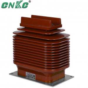
LCZ-35 50-1500A Indoor High Voltage Dry Current Transformer


Product Description
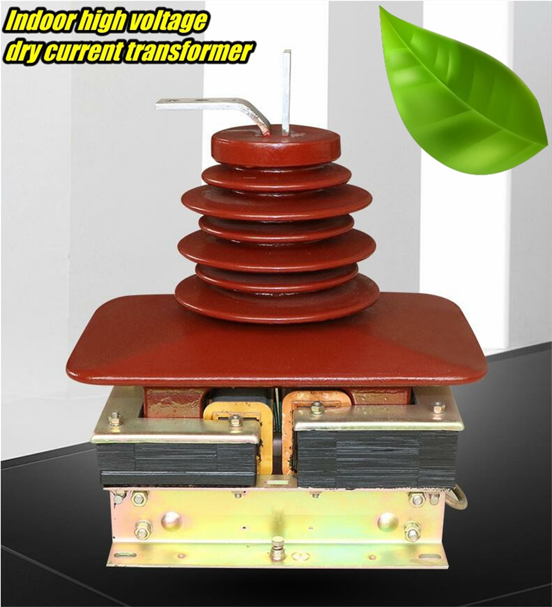
LCZ-35 current transformer is a semi-closed insulation casting product, suitable for power system with rated frequency of 50Hz or 60Hz and rated voltage of 35kV and below, as electric energy measurement, current measurement and relay protection. This product complies with IEC44-1 and GB1208 "Current Transformer".
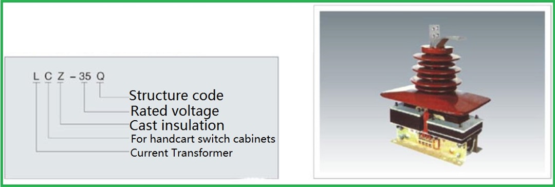
Model Description
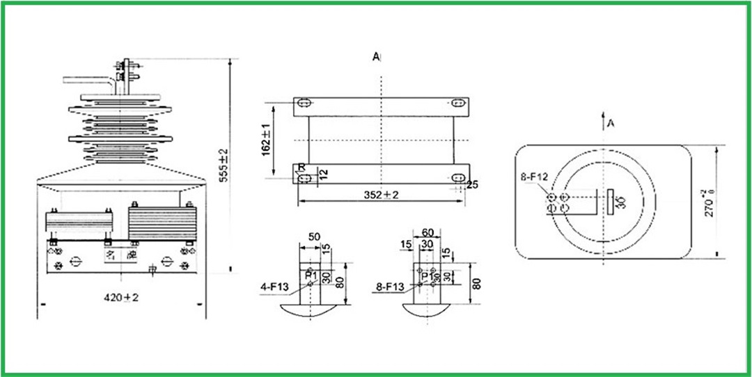
Technical parameters and structure dimensions
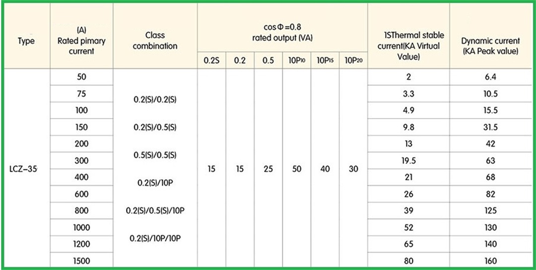
1. The rated secondary current, accuracy class combination, rated output and dynamic and thermal stable current are shown in the table
2. Rated insulation level: 40.5/95/185 Kv
4. The partial discharge level of the product meets the requirements of the GB1208 "Current Transformer" standard.
5. Pollution level: the products in all working conditions meet the requirements of level II pollution.
6. Non-standard products can be customized according to users.
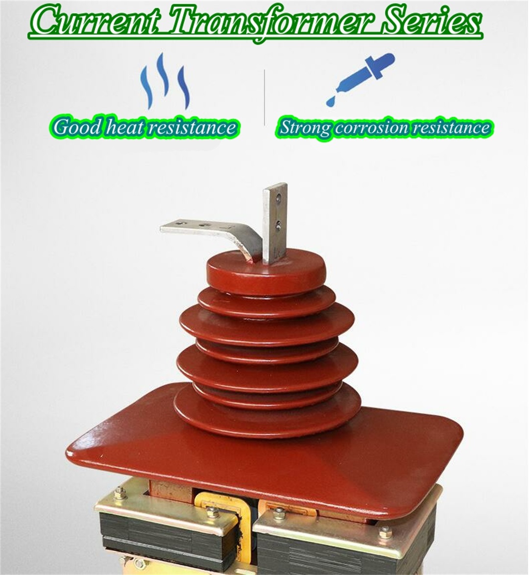
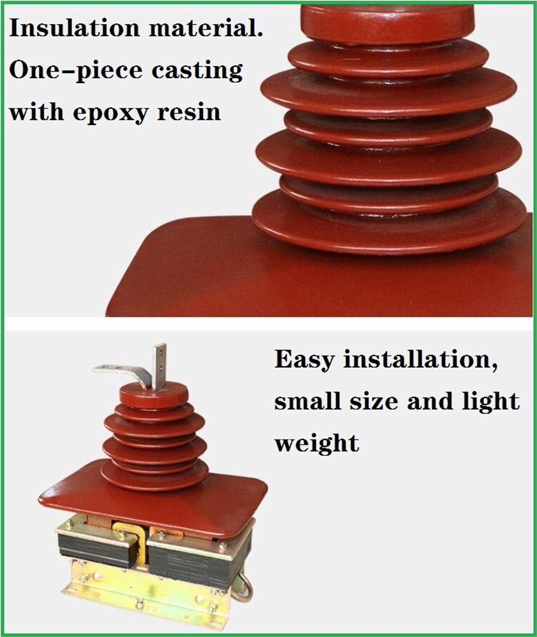
Product features and Instructions for use
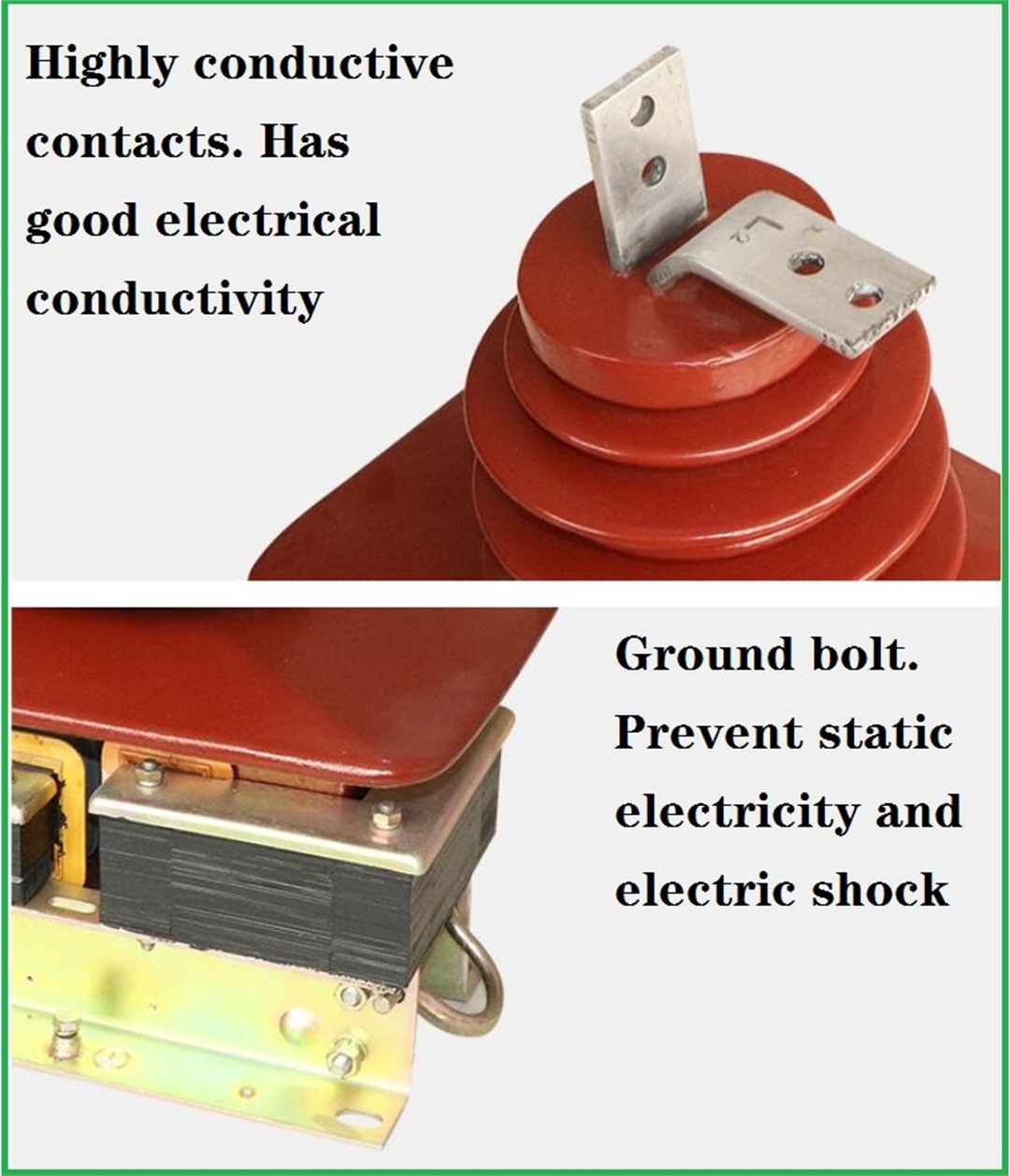
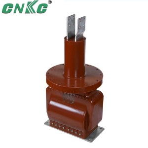
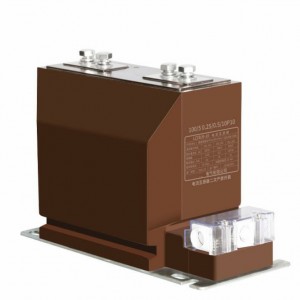
This type of current transformer is of epoxy resin casting semi-enclosed structure. The primary winding and the secondary winding are first cast into one, and then the iron core is inserted into the casting body. The product has excellent insulating properties and moisture resistance. There are grounding bolts and nameplates and four mounting holes for installation on the bottom plate of the product.
normal use conditions:
Installation place: indoors.
Ambient temperature: the temperature is 40℃; the temperature is -5℃; the daily average temperature does not exceed 30℃.
Atmospheric conditions: There is no serious pollution in the atmosphere.
Product Instructions:
1) LCZ-35(Q) The wiring of the LCZ-35 current transformer current transformer should follow the series principle: that is, the primary winding should be connected in series with the circuit under test, and the secondary winding should be connected in series with all instrument loads
2) Select the appropriate change according to the measured current, otherwise the error will increase. At the same time, one end of the secondary side must be grounded to prevent the high voltage on the primary side from entering the secondary low voltage side once the insulation is damaged, causing personal and equipment accidents
3) The secondary side is absolutely not allowed to open circuit, because once the circuit is open, the primary side current I1 will all become magnetizing current, causing φm and E2 to increase sharply, resulting in excessive saturation magnetization of the iron core, serious heat generation and even burning of the coil; , which increases the error. When the current transformer is working normally, the secondary side is similar to a short circuit. If it is suddenly opened, the excitation electromotive force will suddenly change from a small value to a large value, and the magnetic flux in the iron core will show a severely saturated flat top. Therefore, the secondary winding will induce a very high peak wave when the magnetic passes through zero, and its value can reach thousands or even tens of thousands of volts, which endangers the safety of the staff and the insulation performance of the instrument. In addition, the open circuit of the secondary side makes the voltage of the second ary side reach several hundreds of volts, which will cause an electric shock accident if touched. Therefore, the secondary side of the current transformer is equipped with a short-circuit switch to prevent the secondary side from being open. In the process of use, once the secondary side is open, the circuit load should be removed immediately, and then the power outage should be processed. It can be reused after everything is disposed of.
4) In order to meet the needs of measuring instruments, relay protection, circuit breaker failure judgment and fault filtering, etc., all circuits are installed in generators, transformers, outgoing lines, bus sectional circuit breakers, bus circuit breakers, bypass circuit breakers and other circuits. 2 to 8 current transformers with secondary windings.
5) The installation site of the protective current transformer should be set as far as possible to eliminate the non-protection zone of the main protection device. For example: if there are two sets of current transformers, and the location allows, they should be located on both sides of the circuit breaker, so that the circuit breaker is in the cross protection range
6) In order to prevent the busbar failure caused by the bushing flashover of the pillar-type current transformer, the current transformer is usually arranged on the outgoing line or the transformer side of the circuit breaker.
7) In order to reduce the damage caused by the internal fault of the generator, the current transformer used for the automatic adjustment of the excitation device should be arranged on the outgoing side of the stator winding of the generator. In order to facilitate analysis and find internal faults before the generator is integrated into the system, the current transformer used for measuring instruments should be installed on the neutral side of the generator.
Product details
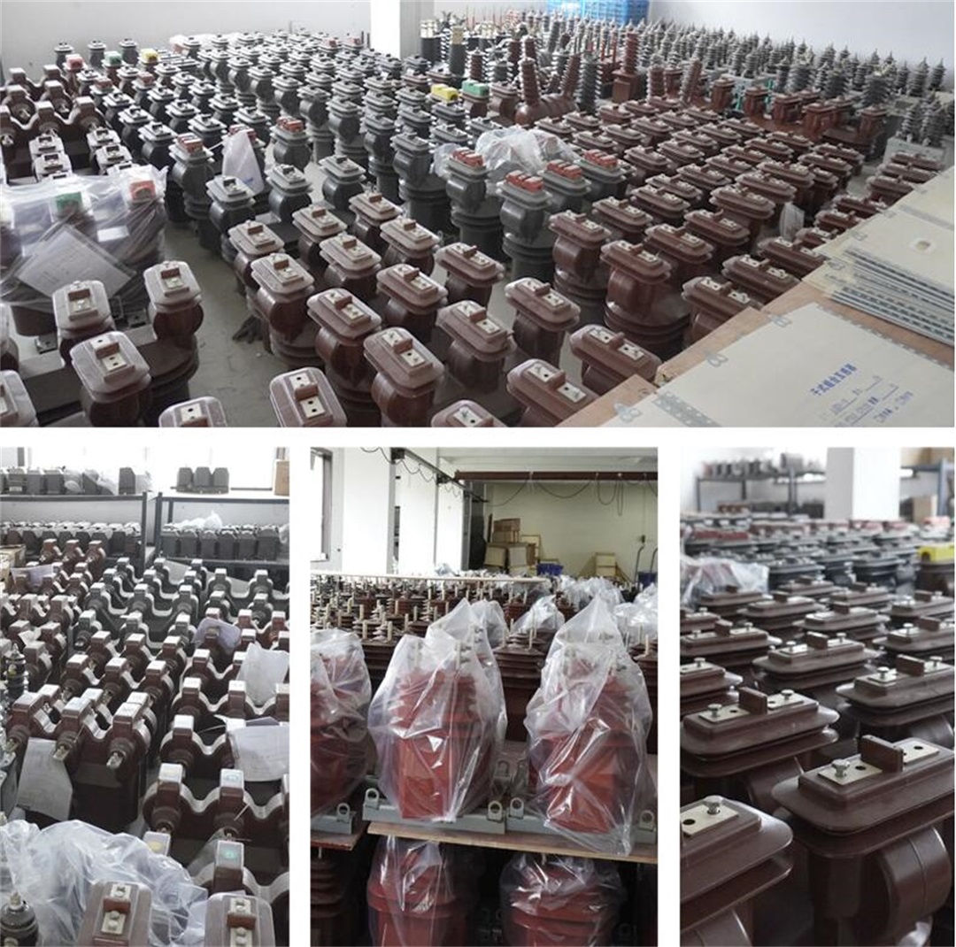
Products real shot

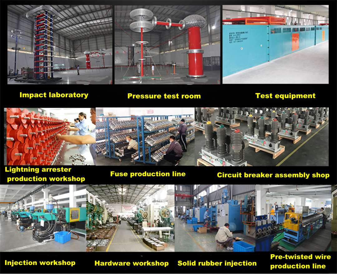
A corner of the production workshop
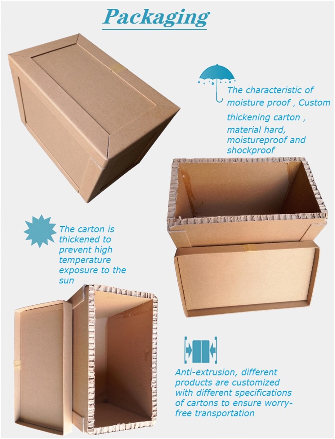
Product packaging
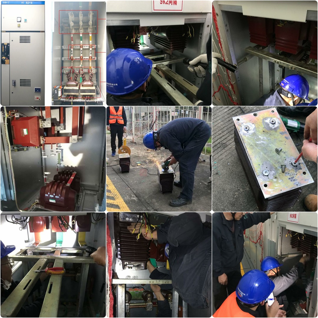
Product application case
Products categories
-
LZZBJ4-35KV 200-500A 1600A Indoor dry type pill...
-
LCWD 35KV 15-1500/5 0.5/10P20 20-50VA Outdoor ...
-
LZZBJ71-35W 35KV 200-2500A Outdoor High Voltage...
-
LXK-80/100/120 aperture 10/35KV indoor HV zero-...
-
LZZB9 24/35KV 200-1250A indoor current transfor...
-
LZZBJ9-10 3/6/10KV 200-2000A High-quality HV ...


